I bought some 24V solar panels cheap, and was looking for a cheap charge controller for them. The CMTP02 was a good price, so I bought one rated at 10A on the chance it actually worked. It did work, but as many people found, the cutoff voltage was higher than desired. Although there are several articles about the CMTP02 online, I couldn't find anyone who had tackled this problem. I decided to reverse engineer the board to find out how it worked and what could be changed to lower the cutoff voltage. There seems to be many variants to this board, but the pictures show similar components in similar places so maybe this is useful to other people.
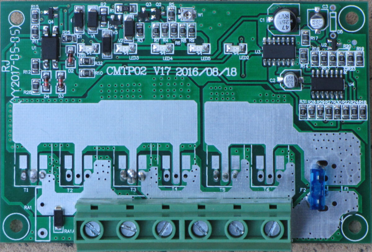
This is the board removed from its case. The other side has 3 TK80E08K3 MOSFETs. These FETs have an on resistance of 7.5 milliohm and maximum current of 70A, adquate for the job if cooled properly. At 10A they should need to dissapate under 1W. There is a video (which I can't find again, I think it was in Spanish) showing the FETs removed from the board and mounted on a fan cooled heatsink, able to handle 40A with no other modification to the board.
There is no CPU, the ICs are an LM324 quad op amp and a CD40106B CMOS Hex Schmitt-Trigger Inverter.
This is the circuit as best I can make out. There may be errors and omissions but there's enough to work out how it works and what to change.
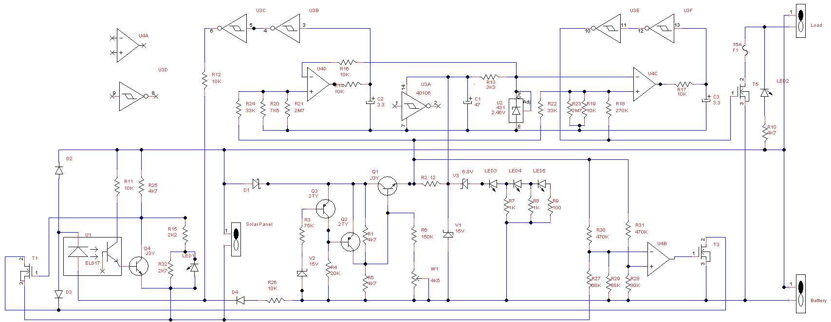
All the +ve terminals are common, the operation is controlled by switching the negative input or output. Most of the circuitry is powered from the output of Q1. For a 12V battery, no current can flow through zener V2 so Q3 is off, Q2 is on. This causes R1 to be bypassed so the base of Q1 is the battery voltage minus the drops through D1 and Q2 so the output of Q1 is slightly lower again. For a 24V battery, V2 conducts so Q3 turns on clamping Q2 off. The base of Q1 now receives half the battery voltage due to the divider R1, R2. The purpose of R6,W1 is not clear. The output of Q1 is also the voltage monitored to determine the battery voltage limits. Note that for a 12V system, the voltage drop through D1,Q1 has to be added to work out the battery voltage when charge limiting occurs.
A reference voltage of 2.45V (or thereabouts) is generated by U2. The op amp U4D compares this to the Q1 output via the divider R20/R21 and R24. The purpose of R21 is not clear, it doesn't seem to be useful. The inputs of U4D are theoreticall balanced when Q1 output is 13.26V, assuming a 2.45 reference and accurate resistors. If Q1 output is lower, The output of U4D goes low, the output of U3C is low, the optocoupler LED is not lit, there is no current to Q4 so T1 is biased on via R25 allowing the solar panel to feed into the system. Once the output of Q1 exceeds a theoretical 13.26V the output of U4D goes high, leading to Q4 turning on which clamps T1 off and there is no feed from the solar panel. There is no hysterisis, once the limiting voltage is reached the feed is shut off. R14 and C2 introduce a small time delay using the hysterisis in the inverters. This limits the number of on/off transitions (guessing - less than a thousand a second). Note that the battery voltage is around 1V higher than the output of Q1, so limiting theoretically starts at a battery voltage of around 14.3V.
The circuit U4B and T3 appear to be protection. T3 is not turned on until the panel voltage is about 0.2V higher than the battery voltage. If the panel has protection diodes to prevent reverse current, it is not clear this is necessary. And at 10A, T3 needs to dissapate 2W with limited heatsinking.
The circuit U4C and T5 are undervoltage protection, cutting supply to an attached load. This is only useful if all loads are routed through the controller, which is fused at 15A. I shall not be using this, I am running an inverter that draws over 100A and has its own undervoltage protection.
With a 12V 35W panel (delivering around 2A), the controller limited charge at 14.54V according to my voltmeter (caveat - not expensive, could be some % inaccurate). The voltage drop through D1,Q1 was around 1V (1.02), the output of Q1 was measured at 13.51V. The reference voltage (out of U2) was measured at 2.49V rather than specification 2.45V which says the theoretical value of Q1 output should be 13.48V - close enough to the actual value.
The string of red LEDs are a very crude indicator of charge. Voltages were measured when the charge limit was reached. All the LEDs were brightly lit. The input voltage to the zener V3 was 13.26V, voltage across R7, R8, R9 was 4.43V, 2.49V, 0.57V. Using the values of the resistors, can calculate the current through each LED as LED3 - 12.6mA, LED4 - 8.2mA, LED5 - 5.7mA. LED5 only lights when battery is charging, and goes off when the battery charge is around 13.2V (soon after charge is removed). I didn't test to see when LED4 goes out, theoretically around 11V. LED3 should light at less than 10V, so really just indicates a battery is attached. Comparing the brightness of LED3 and LED4 gives some indication of condition. A good battery will have LED4 nearly half as bright as LED3. If LED4 is much dimmer, the battery is not charged up.
Since the charge cutoff is determined by the divider R20/R21 and R24, A parallel resistor to R24 should lower the cutoff. This was tested with a 470K resistor, and the cutoff was reduced to around 13.75V.
Another test was to isolate the -ve end of R21 by scratching the foil away with a pin, then connecting it to the output of U4D. This provides a small amount of positive feedback which creates some hysterisis. The panel is cut off around 13.78V and reconnects around 13.74V. Instead of LED1 flickering constantly it changes only a few times a second at most. This worked well with a good battery but was unpredictable with one that had a high internal resistance.
When I can get another good battery, I shall experiment with the 24V mode, using a 24V 250W panel delivering around 9A.
The controller does not work well if there is some resistance between the controller and battery, or if the battery has high internal resistance.
The red LEDs are a waste of space. When a battery with some charge is connected the green load LED is lit. When a solar panel is connected, the green solar LED is on or cycling. If it is cycling the battery is charged. That's about all we need to know.
If you wish to contact me, email project1 at cashin dot net (no spaces, at is @, dot is .)