A Low Cost Sidereal Clock
Introduction : Overview : Accuracy
Circuit
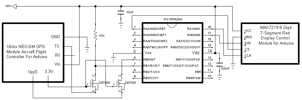
The circuit consists of 3 major components and a few interface components. The major components are:
- Ublox NEO-6M GPS APM2 Module Aircraft Flight Controller For Arduino
- MAX7219 8-Digit Red LED Display Module 7 Segment For Arduino
- PIC16F628A
A search on the Internet using the descriptions will find many sellers of the major components. The 2N7000 FETs interface the 3.3V signals from the GPS to the 5V level required by the microprocessor.
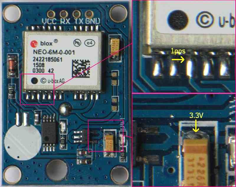
The GPS module does not conveniently provide 1ppS and 3.3V, these require soldering wires to the module directly. This is described below
Note the circuit is not identical to that in the November 2015 issue of Silicon Chip. There are less components due to a software change.
Additional features
- RA3 is an output updated by the TMR1 overflow routine. When the processor enters the main loop, this will output an approximately 4Hz signal. This could be used to determine if the system is running or not.
- RB3 is an output, providing a pulse of about 80mS each sidereal second. The rising edge is within a few microseconds of the calculated time. It is output as long as there is valid input from the GPS, and is not affected by which time is being displayed.
- RB4 is an input, determining which time is displayed. If left open circuit (as shown) the displayed time is LMST. If shorted to earth, the displayed time is UTC
Solder points on the GPS module