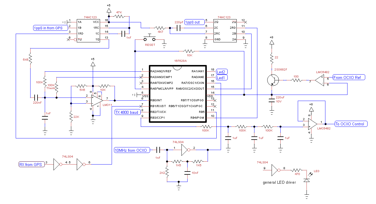
Why describe another GPSDO (GPS Disciplined Oscillator)? Because it it is different. Most designs use a phase locked loop (PLL) to measure the difference between GPS and oscillator, and a digital to analog converter (DAC) to control the oscillator. This circuit does neither. It relies heavily on a microprocessor to provide most of the functionality.
If you came to this page looking for a finished product, you will be disappointed. The circuit was created as a test bed to explore alternate design approaches. It is a working circuit, and with the right OCXO (oven controlled crystal oscillator) is quite capable of maintaining its frequency within 1 part in 1010, and normally closer to 1 part in 1011.
If the technology looks dated, it is. The original circuit was built in 2013 and inspired by an article in Silicon Chip magazine in 2011 which was itself a revision of an earlier design. The project was shelved once the basic concepts were proven as there was little interest in it. This changed in September 2019 when I was encouraged to finish it and write it up. A description should appear in Silicon Chip in 2020, the article can only cover the basics, this website attempts to fill in the details.
The main points of difference are:
1. There is no manual adjustments required. The control voltage to the OCXO is adjusted through the full range with a granularity of less than 1µV
2. The GPS signal and oscillator are compared to the nearest 16nS, over a range of + or - 1µS or 10 cycles of the 10MHz OCXO
3. The control voltage correction is calculated periodically using statistical methods
4. In the long term, the oscillator is locked to the GPS - useful for accurate timekeeping over long periods
5. A form of temperature compensation is used to reduce the effects of changes in ambient temperature.
1. Overview
2. Circuit details
3. Designing for the PIC
4. Source code
The program is written as three PIC assembler modules. There is a lot of documentation in the source code that covers the details.
Processor: PIC16F628A
OCXO: Morion MV89
GPS module: Holux GR-87
All the other components can be bought at most electronics stores.
The circuit is presented "as is". It is the working prototype but is not presented as an example of good design. When it was built, the aim was to get something that worked. The author has no test equipment (unless a multimeter rates as 'test equipment') and this is the first circuit designed from scratch. The power supply is not shown, it is an old switch mode 16V laptop power supply. The various voltages come from off the shelf linear regulators - MC78T12, 7808, 7805. Also not shown, each chip has a bypass capacitor wired between Vss and Vdd.